VLANs with Proxmox and pfSense
VLANs are a great, secure way to segment your network and group compute in any way you want. It allows the creation of multiple LANs with just a single physical switch, without interference from each other. This means that on a single switch, multiple DHCP servers (for example) can co-exist!
In this post, I’ll show you how to set up VLANs within Proxmox using pfSense as our (virtual) router. This can be a good starting template as well if you’ve just started dipping your toes with “homelab-ing”.
Target Topology

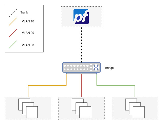
The figure above shows what we’ll be working towards. Since I don’t have any managed switches lying around (yet), the setup will be “emulated” using Proxmox (with a bridge acting as the switch) and a pfSense instance. The topology we’re going to use is also known as the Router on a stick configuration.
Setup
Bridge Creation
To create a bridge, choose your target Proxmox node then “Network > Create > Linux Bridge”. Don’t forget to tick “VLAN aware”.

Leave the CIDRs empty, we’ll let pfSense handle that.
We’ll refer to this bridge vmbr99 from this point on.
Note: If you are running a Proxmox version lower than 6.1, you’ll have to reboot your node for the changes to take effect. If you can’t afford a reboot, follow the steps outlined here.
pfSense VM Setup
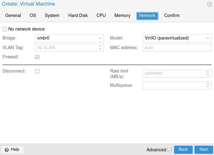
Using the latest pfSense image (download here if you haven’t already), create a new VM. Configure it as you like but make sure to connect the initial NIC to the bridge you are using to access Proxmox (usually vmbr0). This NIC will serve as our “WAN” connection, which will allow us to access pfSense’s webConfigurator.

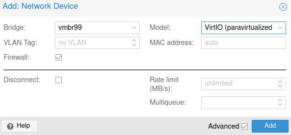
After the VM is created, add a new NIC to the pfSense VM by clicking it then “Hardware > Add > Network Device”. Set the target bridge to the one we’ve created previously.

This NIC will serve as our “Trunk” / “Tagged” connection.
Initial pfSense Setup
Turn on the VM, go through the installation process, and wait until you’ve rebooted to the console. Once in the console, follow the following prompts and answers:
Note: Just for the heck of it, we’ll set up VLAN 10 via the console and the rest (VLAN 20 and VLAN 30) via the webConfigurator.
- Should VLANs be set up now [y|n]? y
- Enter the parent interface name for the new VLAN: vtnet1
- If you’re unsure, go to your VM’s “Hardware” and find the MAC address of the NIC connected to
vmbr99(which is vtnet1 in my case)
- If you’re unsure, go to your VM’s “Hardware” and find the MAC address of the NIC connected to
- Enter the VLAN tag (1-4094): 10
- (Enter nothing to finish the VLAN setup)
- Enter the WAN interface name: vtnet0
- If you’re unsure, go to your VM’s “Hardware” and find the MAC address of the NIC connected to the “default” bridge (usually
vmbr0)
- If you’re unsure, go to your VM’s “Hardware” and find the MAC address of the NIC connected to the “default” bridge (usually
- Enter the LAN interface name: vtnet1
- This should be the same interface you’ve specified during the first VLAN prompt.
- Enter the Optional 1 interface: vtnet1.10
- This will be the interface for VLAN 10
Double-check the interface assignments and proceed until you’ve presented with a menu of sorts. Choose option 8 which should present a terminal prompt. Enter pfctl -d (this temporarily disables the firewall rules) and then visit the IP address of the WAN interface using your web browser.
pfSense webConfigurator Setup
On the webConfigurator, log in using “admin” as the username and “pfsense” as the password. Follow the on-screen setup and look out for the following:
- On “Configure WAN Interface”
- Untick
Block RFC1918 Private NetworksandBlock bogon networks
- Untick
- On “Configure LAN Interface”
- Feel free to assign any address you want. We’ll be using
192.168.99.1/24.
- Feel free to assign any address you want. We’ll be using
After the pfSense Wizard setup, you’ll need to go back to the Proxmox console for pfSense and type pfctl -d again.
To get rid of the pfctl -d “workaround”, we’ll have to add a firewall rule on our WAN’s interface. To do so, simply go to “Firewall > Rules > WAN” and click add. For the source choose “WAN net” (since we’re accessing the router from the WAN network) and choose “This firewall” for the destination. Save the rule and click “Apply Changes”.
Before proceeding, go to “Interfaces” and you should have the following:

VLAN 10 Setup and Testing
Before we create VLAN 20 and VLAN 30, let’s set up VLAN 10 first and validate if it works. To continue with the setup, go to “Interfaces > OPT1” and do the following:
- Tick
Enable interface - On “IPv4 Configuration Type” choose Static IPv4
- We’ll be assigning a DHCP Server for this VLAN
- On “IPv4 Address” enter any address you want. We’ll be using
192.168.110.1/24- This will be the IP Address of VLAN 10’s Gateway (and the corresponding subnet)
- Click Apply Changes
- Go to “Services > DHCP Server > OPT 1”
- Tick
Enable DHCP server on OPT1 interface - On “Range”, enter the subnet range you want. We’ll be using
192.168.110.20 ~ 192.168.110.150 - Save
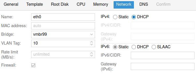
To test, spin up a compute (either a VM or container) and configure as you like. When you reach the network tab:
- Set the bridge to
vmbr99 - Set the VLAN Tag to
10 - If creating an LXC Container, set IPv4 to DHCP

Logging in the compute and doing either ip a or ifconfig yields:
...snip.. |
Which is what we’ve expected.
Now, you might’ve tried to ping something on the internet (or within your local network) and noticed that it’s not going anywhere. To fix that:
- Go back to the webConfigurator and go “Firewall > Rules > OPT1”
- Add a firewall rule that allows any Protocol, Source, and Destination
- Save the rule and apply the changes
Note: pfSense is a stateful firewall so you only need to apply the rule one-way.
If you’ve already applied the firewall rules above and you are still not getting through, go “System > Advanced > Networking” and untick Disable hardware TCP segmentation offload and Disable hardware large receive offload. This optional step depends on the NIC model you’ve chosen (E1000, VirtIO, etc.) during the compute setup.
VLAN 20 / 30 Setup and Testing
Let’s now create the rest of the VLANs. To create VLAN 20 and 30:
- Click “Interfaces > Assignments > VLANs”
- Click “Add”
- Set
Parent Interfacetovtnet1(or whatever the LAN interface is) - Set
VLAN Tagto 20 (VLAN 20) and an optional description then save. - Click
Interface Assignmentsthen add the VLAN you just created. - Click “Interfaces > OPT2” (or whatever interface name VLAN 20 has).
- Tick
Enable interface. - Set
IPv4 Configuration TypetoStatic IPv4. We’ll use192.168.120.1/24.- Just like in VLAN 10, this is going to be the IP Address of VLAN 20’s Gateway (and the corresponding subnet)
- Click “Save” and “Apply Changes”
- Click “Services > DHCP Server > OPT2” (again, whatever the interface name VLAN 20 has).
- Tick
Enable - Set the range of IPs to be handed out. We’ll be using
192.168.120.20 ~ 192.168.120.150 - Then finally, click Save
Perform the same steps for VLAN 30 (substituting 20 with 30 and 192.168.120.1 with 192.168.130.1).
To test, we’ll spin up compute the way we did for VLAN 10 only this time, set the VLAN Tag to either 20 or 30. Performing ip a should yield:
...snip.. |
and
...snip.. |
To enable each compute to talk to each other, don’t forget to set up the matching firewall rules.
Congrats! With this, you can now incorporate (more) VLANs into your network for increased security (and lockdown those pesky IoT devices better). If you need more inspiration, the folks over at /r/homelab can provide you with a lot of creative juice you need for that next big project ;). Viel Spaß!