Remote LAN access with WireGuard
Translations: 简体中文 (Thanks Zhen!)
(2024-09-10) Update: Remote LAN Access with Tunneled Outbound using WireGuard
In this episode, let’s go over how to set up a simple but secure tunnel (read: VPN) to your local LAN (read: homelab) using WireGuard. We’ll be going with the VPS route so we don’t have to expose any ports to the internet.
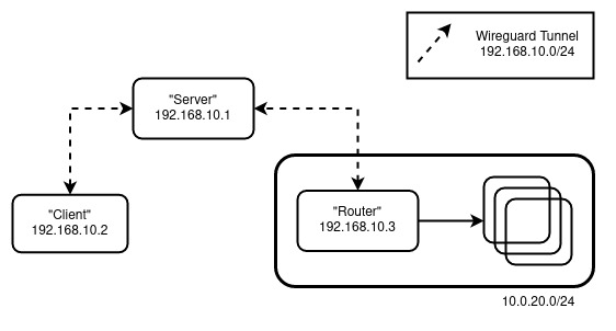
We’ll be emulating the following setup:

The Cast:
- “Router” - The machine that will serve as the gateway (inwards) to your LAN
- “Server” - The machine with a publicly accessible IP that all clients will connect to. Also known as a “Bounce Server”
- “Client” - You, trying to connect to your LAN remotely somewhere
Boring (get it?) Setup
Note: All the machines here are Ubuntu-based. Adjust the setup accordingly to your distro of choice.
“Server” and “Router”
For “Server” and “Router” perform the following:
sudo apt update && sudo apt upgrade |
Note: To persist IP Forwarding, edit /etc/sysctl.conf with net.ipv4.ip_forward=1
For the “Server”, create /etc/wireguard/wg0.conf with:
[Interface] |
For the “Router”, create /etc/wireguard/wg0.conf with:
[Interface] |
Note: Replace ens18 with the appropriate interface
Enable the interface by wg-quick up wg0 and then check the status by wg show.
At this point, we can perform a quick sanity check. On my setup, running mtr 10.0.20.1 on the “Server” yields:
Packets Pings |
“Client”
On the “Client” perform the following:
sudo apt update && sudo apt upgrade |
Then create /etc/wireguard/wg0.conf with:
[Interface] |
Enable the interface by wg-quick up wg0 and then check the status by wg show. We also need to update the wg0.conf of “Server” with “Client” as a new peer.
Update “Server” with:
[Interface] |
Note: Don’t forget to restart the wg0 interface by wg-quick down wg0 && wg-quick up wg0
Now, running mtr 10.0.20.1 on the “Client” yields:
Packets Pings |
Which follows the “Client” -> “Server” -> “Router” flow that we want.
Config digging
Most of the “routing” is dictated by the [Peer] AllowedIPs configuration. It governs what can go in and go out of the tunnel. For example, given the following setup:
Peer A
[Interface] |
Peer B
[Interface] |
If Peer A attempts to connect to (for example) 192.168.10.11, since the address is within 192.168.10.0/24, it will be allowed to “enter” on Peer A’s side. When it comes out of Peer B’s side, it will be dropped since it is not within 192.168.20.0/24. It gets a bit confusing when a “netmasked” [Interface] Address comes into play. While [Interface] Address can also influence the “routing” (if netmasked), the “final decision” is always up to the [Peer] AllowedIPs. For example:
Peer A
[Interface] |
If we try to connect to 192.168.10.11, it will be “routed” to this interface because of 192.168.10.1/24, but it will not be allowed inside the tunnel (dropped) since it is not within 192.168.20.0/24.
To demonstrate further, using our setup:
- Update
[Peer] AllowedIPsof “Router” fromAllowedIPs = 192.168.10.0/24toAllowedIPs = 192.168.10.2/32
“Client” still can reach 10.0.20.1/24 albeit “Server” cannot anymore.
- Update
[Peer] AllowedIPsof “Client” fromAllowedIPs = 10.0.20.0/24, 192.168.10.0/24toAllowedIPs = 10.0.20.0/24
“Client” is still able to reach 10.0.20.1/24, but mtr does not display the IPs of the host in the chain anymore (e.g.)
Packets Pings |
The reason is that when the hosts try to “reply” to mtr, the packets are dropped. After all, “Server” (192.168.10.1) and “Router” (192.168.10.3) are not within the new [Peer] AllowedIPs range of “Client”.
Till next time!